Comparison of Observed and Model Magnetic Fields at High Altitudes above
the Polar Cap: POLAR Initial Results
X.-W. Zhou, C. T. Russell, Guan Le, and N. Tsyganenko
Originally published in:
Geophysical Research Letters, 24, 1451-1454, 1997.
Abstract
Data obtained from the high altitude, polar
orbiting spacecraft, POLAR, are compared with the
latest version of the data-based magnetospheric magnetic
field model. The data generally agree well with the
model. The major directional discrepancies at high
altitudes are near the dayside cusp and on the "open"
field lines over the polar cap, especially close to the
boundary of the polar cap. Near the cusp, the
agreement is improved if a stronger solar wind dynamic
pressure and more negative IMF By and Bz are used
as the model input parameters, than was actually
observed. The field measured in the vicinity of the
polar cusps is generally weaker than predicted by the
model. Close to noon the spacecraft enters a region of
additional structured field depression that appears to be
the polar cusp proper. Within the limited statistics
presented here, the invariant latitude of the cusp appears
to be controlled by the north-south component of the
IMF and the broad depression appears to be controlled
by the tilt of the dipole.
Introduction
An accurate magnetic field model is an important tool
for probing the physical processes in the magnetosphere.
Quantitative models based on large sets of spacecraft data,
combined with the standard IGRF models for the internal
field have been widely used during the last years. The
data-based models provide better accuracy in the regions with
a good coverage by magnetometer measurements and are less
well constrained in the regions with sparser sampling or no
data at all.
In comparison with the low-latitude magnetosphere, the
high-latitude region is still far less covered by magnetometer
measurements. So far, the distant polar magnetosphere was
explored only by HEOS (mainly, HEOS 2) and Hawkeye 1
spacecraft. Hedgecock and Thomas [1975] described the
average magnetic field configuration in the polar and near
tail regions by using HEOS data. They also compared HEOS
data with the Mead-Fairfield [1975] model, showing that the
model field is too strong in the high-latitude polar region.
Farrell and Van Allen [1990] identified the polar cleft region
at large radial distances by locating the region where
Hawkeye 1 measured strong negative deviations of the
magnetic field strength from that of the dipole field. These
regions of negative depression relative to the dipole field
strength were generally adjacent to the magnetopause.
Fairfield [1991] compared the data of IMP and HEOS
magnetometers with the field given by the models of
Tsyganenko and Usmanov [1982] and Tsyganenko [1987].
He also found that the models frequently predicted too large
a field strength in the high-latitude cusp region on the
dayside, due to their inability to account for the diamagnetic
currents associated with the dense polar cusp plasmas.
The POLAR Magnetic Field Experiment (MFE) [Russell
et al., 1995] provides a new opportunity for the improvement
of magnetic models in the magnetosphere. The POLAR
spacecraft is in a high-latitude, high-altitude orbit with a
perigee of 1.8 Re, an apogee close to 9 Re, and a period of
17.5 hours. In contrast to HEOS and Hawkeye, POLAR
encounters the cusp at lower altitudes and seldom reaches the
vicinity of the magnetopause.
In this study, we examine in detail one typical orbit,
comparing the POLAR data with the T96_01 version of the
data-based magnetic field model [Tsyganenko, 1996]
combined with the IGRF 95 internal field. We will
demonstrate the existence of a depression of the magnetic
field in the vicinity of the polar cusp, as compared with the
reference field given by the T96_01 and IGRF 95 models,
and show how one can identify the entry into the cusp proper
by using the magnetometer data. The T96_01 model is
largely different from all previous representations of the
distant magnetic field in that: (i) it explicitly includes a
realistic analytical magnetopause, controlled by the solar
wind pressure, (ii) it incorporates the effects of Region 1 and
2 Birkeland currents, (iii) it allows for an IMF-controlled
interconnection between the terrestrial and solar wind
magnetic fields across the boundary, (iv) it is driven by the
solar wind pressure, IMF By/Bz, and the Dst-index, so that
the field components are continuous functions of those input
parameters, in contrast to earlier models, binned by the
Kp-index only.
Model Comparison over an Orbit
To evaluate the accuracy of the model, we use the
inclination and declination angles and the residuals of the
total field between the data and the model
( BT=BTPOLAR-BTT96). The inclination angle is defined as
the angle between the field and the radius vector minus 90o.
Equivalently it can be defined as the angle between the local
horizontal plane and the B vector. The declination angle is
measured in the horizontal plane about the radius vector.
The declination is zero when the projection of the field in the
horizontal plane is northward and 90o when the horizontal
component of the field points eastward in the direction of the
Earth's rotation. When the magnetic field lies close to the
horizontal plane, and the inclination is zero, the declination
angle gives a good measure of the twist of the field from the
magnetic meridian. But in the vicinity of the cusp when the
inclination approaches 90o, the declination angle can be very
sensitive to small variations in the field direction. Thus we
also show the total angle between the observed and model
fields.
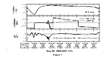
Figure 1 shows the inclination, declination, the
difference in field magnitude ( BT) and the angle between
the model and the measured magnetic field vectors for a
typical POLAR orbit (0000-1730 UT, May 26, 1996). The
solid traces are the observed angles and difference of field,
dotted traces are inclination and declination of the IGRF 95
field. The dashed traces are the inclination and declination
of the IGRF plus the T96_01 external magnetic field. For
the T96_01 model, we use Dst=0, and the observed solar
wind conditions from 0400-0700 UT. The solar wind
dynamic pressure and IMF components observed by WIND
spacecraft at this time were 2 nPa, and IMF By=-4 nT,
Bz=1.5 nT. The standard deviation about these average
values for IMF By, Bz and solar wind dynamic pressure
were 1.35 nT, 2.44 nT and 0.12 nPa respectively. Overall
good agreement between the data and models can be seen in
this figure. For most of the time, the angular departure
between the model and the measured fields is less than 4
degrees. The biggest angular departure is about 16 degrees
in the region of the polar cusp and immediately above it. At
low altitude below 6 Re, the direction of the field is
governed principally by the internal field so no discernible
difference is seen between the models and the data. Even
the total field is very close to that of the model at perigee.
Above 6 Re, the inclination and declination angles found
from the T96_01 model agree much better with the Polar
MFE data than the angles based on IGRF 95 model only,
especially at high altitudes, as can be seen during the period
0600-1230 UT. From 0300 to 0600 UT in the neighborhood
of the polar cusp, a depression in the field is quite
conspicuous. We will examine this region in greater detail
below.
Overview
 Figure 1. (top) Inclination angles from Polar MFE data (solid trace), IGRF 95 model (dotted trace), and T96_01 model (dashed trace); (second panel) declination angles; (third panel) difference between Polar MFE data and T96_01 field. The input parameters of the T96_01 model are: Dst=0, IMF By=-4nT, IMF Bz=1.5 nT, Dyn=2 nPa.
|
Cusp Region
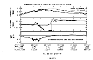
 Figure 2. Similar to Figure 1, but the IGRF 95 trace is not
included. The thick dashed traces are values from T96_01
model with Dst=0, Dyn=2 nPa, and simultaneous IMF By
and Bz. The thin dashed traces are values from T96_01
model with parameters Dst=0, IMF By=-4 nT IMF Bz=1.5
nT, and Dyn=4 nPa.
|
As expected and as illustrated in Figure 1, the major
differences between the observed and predicted fields are
concentrated near the polar cusp. The size and direction of
the distortion of the field can be best visualized in terms of
angles and of the residual deviation from the model. The
data for the period 0400-0900 UT on May 26, 1996, are
shown in Figure 2. The solid traces are the magnetometer
data; thick dashed traces are the values from the T96_01
model for Dst=0, Dyn=2 nPa and simultaneous IMF By and
Bz which are measured by the WIND spacecraft. The time
lag we used is: T=(x-10Re)/400, where x is the position of
WIND spacecraft in GSM in km and T is in seconds. The
oscillations in the model are caused by the varying input
parameters in the solar wind. The thin dashed traces are
from T96_01 model with parameters Dst=0, Dyn=4nPa, IMF
By=-4 nT, Bz=1.5 nT. Near the cusp region, the model
overestimates the magnitude of the magnetic field by up to
about 20 nT in the smoothly varying region and the field is
highly twisted away from the T96_01 model predictions after
the cusp itself is encountered. The deeper, structured
depression of the magnetic field (up to 60 nT) from
0450-0540 UT is the cusp or cleft. This structured depression
begins about 1120 MLT and extends to noon MLT. The
vertical dashed lines in this figure indicate the period when
the HYDRA instrument observes magnetosheath-like electron
[J. D. Scudder, personal communication, 1997]. This
confirms that the deep depression occurs in the cusp. The
inclination that measures the distortion of the field out of the
horizontal plane indicates the field is slowly becoming
oriented radially inward as the spacecraft moves poleward of
the cusp. The declination angle shows that the initially
northward field swung toward dusk as the cusp proper was
encountered. Then it returned northward at 0520 UT and
rotated dawnward and then pointed due south, turning away
from southward to almost duskward by 0900 UT.
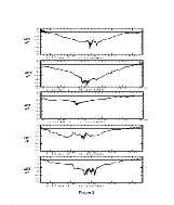
 Figure 3. The residual of magnetic field magnitude between
Polar MFE and T96_01 model for five orbits in May 1996
near the cusp region. The vertical lines show where
magnetosheath-like electrons were observed by the HYDRA
instrument.
|
Figure 3 shows a set of near-cusp crossings. We use
Dst=0 and the real IMF and solar wind conditions in this
figure. The vertical lines show the periods when
magnetosheath-like plasma is seen. The broad field
depression surrounding the cusp is seen on almost every pass
through the cusp region. The additional structured depression
in the center of the cusp region occurs much more rarely. Table 1 shows the time and location of these crossings along
with the solar wind dynamic pressure and IMF By and Bz.
The local time and invariant latitude are given for the
northern foot of the field line traced by using the T96_01
model. The BT base column gives the largest depression
seen in the broad region surrounding the cusp. The BT
min is the depression of the field reached in the structured
cusp.
Table 1
Although we have only a few data points, there is an
indication of a possible correlation between the depression
( BT) and the Earth's dipole tilt angle. Indeed, the biggest
and the smallest depressions occur when the dipole is tilted
away from and toward to the Sun, respectively. The cusp is
at its most equatorward latitude for southward IMF and at its
most poleward position for northward IMF. This correlation
is consistent with that observed by Hawkeye [Farrell et al,
1990] and previous cusp studies [e.g., Russell et al, 1971].
Such a depression has also been seen at low altitudes by
Erlandson et al [1988] in the Viking observations. We have
too few cases at present to determine if there are solar wind
dynamic pressure effects and IMF By effects adding to the
apparent tilt angle and IMF Bz effects.
Varying the Parameters of the Model
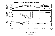
 Figure 4. (top) Inclination angles from Polar MFE data
(solid trace); T96_01 model with IMF By=Bz=0 nT (thin
dashed trace); and T96_01 model with IMF By=Bz=-5 nT
(thick dashed trace); (middle) declination angles; (bottom)
difference of BT between Polar MFE data and T96_01 model.
|
As mentioned above, we have used the parameters as:
Dst=0, Dyn=2 nPa and simultaneous IMF in Figure 2,
corresponding to those measured on May 26, 1996, by the
WIND spacecraft. However, if we change these parameters
away from their observed values, we can improve the
agreement. It is our purpose here not to improve the model
but rather illustrate the direction of such future
improvements might take. Figure 4 shows the inclination
and declination and the residual field strength for the same
Dst=0 and Dyn=2 nPa, but for different IMF conditions, in
the same format as in Figure 2. Here, the model field for
negative IMF By and Bz (thick dashed traces) fits the MFE
data much better than that for By=Bz=0 over the period
0530-0800 UT. However, as shown in Figure 2, if we
compare the data with the model for Dst=0, IMF By=-4,
Bz=1.5, and dynamic pressure of 4 nPa, i.e. twice larger than
observed, the agreement can also be improved. For
declination angles, the agreement can be greatly improved
over the period 0520-0830 UT, although there are still large
differences in the immediate vicinity of the structured polar
cusp. The agreement in the inclination angle is also
improved, and BT is improved at the dip by about 10 nT,
in comparison with that for dynamic pressure of 2 nPa in
Figure 2. In short, according to the model the field over the polar cap is distorted by the solar wind as if the solar wind
and IMF had greater values than actually observed.
The most likely reason for the improvement of the
results by the above modification of the input parameters is
an underestimate of the near-cusp Region 1 field-aligned
currents by the model. Both the IMF components (By and
Bz) and the solar wind pressure were used for
parameterization of the model Region 1 Birkeland current
amplitude, so that larger values of the IMF clock angle and
of the pressure yield larger Birkeland current, which is
responsible for the 180-degrees excursion of the declination
angle in Figures 2 and 4 .
The POLAR data imply that the
dayside Region 1 current is localized even closer to the noon
meridian plane, than assumed in the field model.
Summary
The early magnetic field measurements on POLAR
illustrate that the T96_01 model provides a good overall
approximation to the field in high-altitude, high-latitude
magnetosphere. However, the T96_01 model overestimates
the field in a large region surrounding the polar cusp, and
within this region there is an additional deep depression near
noon, which we attribute to the cusp itself. The depth of the
broad depression varies with universal time, which we
interpret as due to the variation of the geodipole tilt angle
with respect to the solar wind direction. The structured
region within this broad depression moves equatorward for
increasing southward IMF Bz. The field is twisted near this
region possibly due to the field aligned currents. Using the
model with a higher dynamic pressure or with more negative
IMF Bz, than actually observed, gives a better agreement
with the data. This suggests that the actual intensity of the
dayside Birkeland currents at the time of the measurements
was substantially larger and/or they were concentrated closer
to the dayside cusps, than according to the model.
 Figure 5. Similar to Figure 2, but with input parameters as: Dst=0, IMF By=-4 nT, IMF Bz=1.5 nT, Pdyn=4 nPa.
|
Acknowledgments
The authors wish to thank J. D.
Scudder for making the HYDRA data available to us for the
cusp identification in this paper. This research was supported
by the National Aeronautics and Space Administration under
research grant NAG5-3171.
References
Erlandson, R. E., L. J. Zanetti, T. A. Potemra, M. Andr , and
L. Matson, Observation of electromagnetic ion cyclotron
waves and hot plasma in the polar cusp, Geophys. Res.
Lett., 15 , 421-424, 1988.
Fairfield, D.H., An evaluation of the Tsyganenko magnetic field model,
J. Geophys. Res., 96, 1481, 1991.
Farrell, W. M., and J. A. Van Allen, Observations of the Earth's polar cleft at large radial distances with the Hawkeye 1 magnetometer, J. Geophys. Res., 95, 20,945-20,958, 1990.
Hedgecock, P. C., and B. T. Thomas, HEOS observations of the configuration of the magnetosphere, Geophys. J. R. Astr. Soc., 41, 391-403, 1975.
Mead, G. D., and D. H. Fairfield, A quantitative magnetospheric model derived from spacecraft magnetometer data, J. Geophys. Res., 80, 523-34, 1975.
Russell, C. T., C. R. Chappell, M. D. Montgomery, M., Neugebauer, and
F. L. Scarf, OGO-5 observations of the polar cusp on November 1, 1968,
J. Geophys. Res., 76, 6743-64, 1971.
Russell, C. T., R. C. Snare, J. D. Means, D. Pierce, D. Dearborn, M. Larson, G. Barr and G. Le, The GGS POLAR magnetic fields investigation, in The Global Geospace Mission, 563-582, Kluwer Academic Publishers, Dordrecht, The Netherlands, 1995. See also Space Sci. Rev., 71, 563-582, 1995.
Tsyganenko, N.A., Global quantitative models of the geomagnetic field in the cislunar magnetosphere for different disturbance levels, Planet. Space Sci., 35, 1347-1358, 1987.
Tsyganenko, N.A., Effects of the solar wind conditions on the global
magnetospheric configuration as deduced from data-based field models, in:
Proceedings of the ICS-3 Conference on substorms (Versailles, France,
May 12-17, 1996), ESA SP-389, pp.181-185, Oct. 1996.
Tsyganenko, N.A. and A.V. Usmanov, Determination of the magnetospheric current system parameters and development of experimental geomagnetic field models based on data from IMP and HEOS satellites, Planet. Space Sci., 30, 985-998, 1982.
 Back to CT Russell's page
 More On-line Resources
 Back to the SSC Home Page
 Figure 1. (top) Inclination angles from Polar MFE data (solid trace), IGRF 95 model (dotted trace), and T96_01 model (dashed trace); (second panel) declination angles; (third panel) difference between Polar MFE data and T96_01 field. The input parameters of the T96_01 model are: Dst=0, IMF By=-4nT, IMF Bz=1.5 nT, Dyn=2 nPa.
 Figure 2.
 Figure 3.
 Figure 4.
 Figure 5.
 Back to CT Russell's page
 More On-line Resources