INITIAL RESULTS FROM THE POLAR MAGNETIC
FIELDS INVESTIGATION
C. T. Russell1, G. Le1, X-W. Zhou1, P. H. Reiff2
, J. G. Luhmann3,
C. A. Cattell4, R. L. McPherron1, and M. Ashour-Abdalla1
1. Institute of Geophysics and Planetary Physics, University of California,
Los Angeles,
CA 90095-1567, USA
2. Rice University, Houston, TX 77251, USA
3. University of California, Berkeley, CA 94720, USA
4. University of Minnesota, Minneapolis, MN 55455, USA
Originally published in:
Adv. Space Res., 20, 833-839, 1997.
ABSTRACT
The POLAR magnetic field investigation was designed to provide a high temporal
resolution and high sensitivity measurement of the magnetic field along the
POLAR orbit from perigee at 2 RE to apogee at 9 RE. The objectives of the
investigation include probing the field aligned currents that couple the solar wind
interaction and the tail dynamics to the auroral ionosphere. The launch of the
spacecraft on February 24, 1966 was nominal and the turn on of the instruments
very successful. Comparisons with Tsyganenko's 1995 model of the external
current systems show that at quiet times it reproduces the field well. POLAR is
clearly observing the field aligned current systems and the ring current. On one
occasion when the IMF was strongly northward and the solar wind dynamic
pressure stronger than usual the high altitude, high latitude magnetosphere became
filled with magnetosheath type plasma. This event was probably an encounter
with the polar cusp near the cusp-magnetosheath interface.
INTRODUCTION
The POLAR spacecraft [Acuna et al., 1995] has finished its initial commissioning
phase and is now taking regular observations with most of its instrumentation.
The spacecraft was launched on February 24 with its orbital plane in the local
time sector just premidnight inbound and just past noon outbound. The orbital
plane crossed the noon-midnight meridian on April 10. The satellite is spin
stabilized with its spin axis perpendicular to the orbit plane. Since the orbit has
a high inclination, the orbital plane is nearly in the magnetic meridian. Thus, the
magnetic field lies principally in the spin plane on a typical orbit in which the
spacecraft stays well within the magnetosphere. Every six months the spin axis
is rotated by 180o for thermal reasons.
The magnetometer is performing nominally, recording data completely around the
orbit from perigee at 2 RE to apogee at 9 RE. Two projections of a typical orbit
on March 28, 1996 are shown in solar magnetic coordinates in
Figures 1a and 1b.
Figure 1c shows the distance of the spacecraft from the Earth-Sun line plotted
versus the distance along the Earth-Sun line for the orbit on March 16, 1996. The
thick trace shows the expected magnetopause position. The dashed line shows the
expected position of the spacecraft relative to the magnetopause for the solar wind
pressure conditions measured by the WIND spacecraft. The orbit here has been
scaled by the sixth root of the solar wind dynamic pressure. We have not
accounted for the time delay between the WIND measurements and the
magnetospheric arrival of the plasma and field. Here that delay was nominally 25
min.
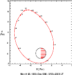 |
Fig. 1a.
Noon-midnight (X-Z) projection of POLAR orbit on March 28, 1996 in solar magnetic
coordinates.
|
 |
Fig. 1b. Dawn-dusk (Y-Z) projection of POLAR orbit on March 28, 1996 in solar magnetic
coordinates.
|
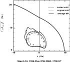 |
Fig. 1c. Distance from the Earth-sun line versus distance along Earth-sun line in solar
magnetospheric (or solar ecliptic) coordinates for the POLAR orbit of March 16,
1996. Nominal location of the magnetopause is shown. Scaled orbit (dashed line) shows the
expected location of the spacecraft relative to the magnetopause for the solar wind dynamic pressure
observed by the WIND spacecraft, obtained by scaling by the sixth root of the
dynamic pressure.
|
In this paper we examine the initial operations of the magnetic fields experiment
(MFE) on the polar spacecraft and show examples of some of the initial results.
MAGNETOMETER DESCRIPTION
The magnetometer [Russell et al., 1995] consists of two orthogonal sensors
mounted on a boom at distances of 5.225 and 7.177m from the center of the
spacecraft, together with electronics on the main body of the spacecraft. The
inboard magnetometer has a maximum range of 46,700 nT with a lower gain
setting of 5860 nT. The outboard magnetometer has a maximum range 5525 nT
with a lower gain setting of 694 nT. The data are digitized to 16 bits. The finest
digitization is ± 11 pT and the coarsest is ± 700 pT. The magnetic field is
sampled at 1000 Hz internally and averaged to 100 Hz. These data are distributed
internally to the other instruments and made available for internal storage in the
snapshot mode. Initially data were transmitted to Earth at a constant rate of 8.3
Hz or 120 msec per sample. Every 6-s spin a sample is taken from the regular
data stream just after the sun sensor crosses the solar direction. Thus, this value
is within 120 msec of the sun crossing. Later we plan to retrieve this sample from
the 10 msec data stream. In either case knowledge of the exact time of the
magnetic sampling and the exact time of the sun crossing allows the
reconstruction (by a small rotation) of the field vector at the time of the sun
crossing (assuming no temporal variations).
The magnetometer's internal clock runs asynchronously with the spacecraft clock.
This choice was made to minimize noise sources within the magnetometer and an
extremely precise and low noise instrument was thus produced. In order to
synchronize the clocks a posteriori, we find specific patterns of the number of
words per major frame. These occur about once every 15 minutes, and at these
times, the relative timing of the magnetometer clock and the spacecraft clock are
known to 1 msec. The relative clock rates change slowly with time due to aging,
temperature changes and updating of the spacecraft clock. This timing
information will be made available to all investigators and the clock rate will be
included in the key parameter data. Information on the operation of the
instrument is being maintained on the MFE world wide web page http://www-
ssc.igpp.ucla.edu/polar/Welcome.html
A TYPICAL ORBIT
Figures 2 a, b,
c, and d
show the magnetic field measured by the POLAR
magnetometer in solar magnetic coordinates on March 28, 1996 together with the
recent Tsyganenko 1995 magnetic field model developed and added to the
International Geomagnetic Reference Field (IGRF 1995) model at epoch of date
[N. A. Tsyganenko, personal communication, 1995]. Solar magnetic coordinates
have their Z direction along the Earth's magnetic dipole axis and the solar
direction lies in the X-Z plane. The measurements and the model are
indistinguishable on this scale.
 |
Fig. 2a.
Magnetic field strength observed by the POLAR spacecraft on March 28, 1996 together with
the predicted field strength obtained from the 1995 model by N.
Tsyganenko of the external currents systems added to the IGRF 1995 internal field for epoch 1996.
|
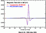 |
Fig. 2b. The X component of the magnetic field in solar magnetic
coordinates observed and modeled for March 28, 1996. In this
coordinate system the z-direction is along the northward pointing magnetic dipole axis; y is
perpendicular to the dipole axis and the direction to the sun; and the x-direction is in
the plane containing the dipole axis and the solar direction completing a right handed
set.
|
 |
Fig. 2c. The Y component of the magnetic field in SM coordinates,
observed and modeled, for March 28, 1996.
|
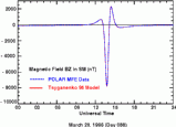 |
Fig. 2d. The Z component of the
magnetic field in SM coordinates,
observed and modeled, for March
28, 1996.
|
Figure 3a and b
show the difference between the model and the observations
rotated into a field-aligned coordinate system in which the Z-direction is along the
model magnetic field, the Y-direction is eastward in the direction of the Earth's
rotation and X-direction forms a right-handed set, pointing to higher L-values. In
Figure 3a only the IGRF model field has been
subtracted while in Figure 3b the
Tsyganenko [1995] model of the external currents for Kp=3 and Dst=0 has been
additionally removed. The residual fields are significantly better at high altitudes
when the Tsyganenko model is used. At low altitudes around perigee near 1400
UT, we see a significant twist in the field in the X-Y plane perpendicular to the
main field. This could be caused by a 0.8° error in the pointing angle of the
magnetometer or a 12 msec error in the timing and we are not prepared to
comment on it at present. Along the magnetic field direction there is a double
depression in the field below the value expected from the model. We do not
know any errors that could lead to such a signature. Moreover, the high altitude
portion of this signature is removed when the Tsyganenko model is used. This
observation suggests that the feature is associated with the quiet day ring current
and that the Tsyganenko model does not completely remove the effects of the ring
current in the innermost magnetosphere.
 |
Fig. 3a.
The difference between the observed magnetic field and the IGRF 1995 model expressed in
field-aligned coordinates on March 28, 1996. In this system the z axis
is along the model magnetic field; the y axis is perpendicular to the field and eastward; and x completes
the right handed system and is roughly outward.
|
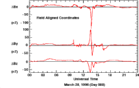 |
Fig. 3b. The difference between the observed magnetic field and the
IGRF 1995 plus Tsyganenko 1995 models expressed in field-aligned
coordinates on March 28, 1996.
|
FIELD ALIGNED CURRENTS
Figures 3a and b
show positive and negative deviations of the Y or eastward
component of the magnetic field at about 10 UT and 16 UT respectively. The
former event is shown more clearly in
Figures 4a and b that show just the Y
component of the magnetic field and the inclination and declination of the
magnetic field respectively. The inclination angle is the angle between the field
and the radius vector less 90° i.e.,
I = cos-1
(Rxbx + Rzbz)-90o where (Rx, 0, Rz)
and (bx, by, bz) are unit vectors in the direction of the radius vector and the
magnetic field respectively in the local dipole meridian coordinate system. The
inclination may also be described as the angle between the local horizontal plane
and the magnetic field direction. The declination angle is measured in the
horizontal plane about the radius vector i.e.,
D=tan-1 [by/(Rxbz - Rzbx)]. The
current system responsible for the field change seen here at 0950 UT is flowing
on the nightside of the Earth and appears to mark the boundary between the
closed dipolar magnetic field lines of the magnetosphere proper and the expanding
polar cusp field lines with perhaps only one foot on the Earth.
 |
Fig. 4a. The eastward field magnetic component of the
difference between the observations and the IGRF plus Tsyganenko
model for the period 0930-1230 UT
|
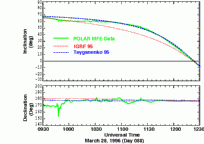 |
Fig. 4b. The inclination and
declination of the magnetic field
for the period 0930 to 1230 UT on
March 28, 1996.
|
The second field aligned current signature shown is a similar pair of
Figures, 5a
and 5b showing the y-component of the difference field in field-aligned
coordinates as well as the declination and inclination of the field. This current is
flowing above the dayside hemisphere and is near the region of the expected polar
cusp. The magnetic field after 1615 UT is twisted to lower declination angles as
if it were being pulled more tailward at higher altitudes.
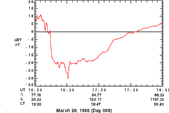 |
Fig. 5a. The eastward magnetic field component of the difference
between the observed field and the Tsyganenko and IGRF model fields for the period 1600 to 1800 UT on
March 28, 1996.
|
 |
Fig. 5b. The inclination and declination of the magnetic field
for the period 1600 to 1800 UT on March 28, 1996.
|
STRONGLY NORTHWARD IMF AND HIGH SOLAR DYNAMIC PRESSURE
Figures 6a and b
show the magnetic field in GSM coordinates and the inclination
and declination angles on May 29, 1996 when the solar wind dynamic pressure
was about 7nPa and the IMF about 12 nT along the GSM Bz direction (K. W.
Oglivie and R. P. Lepping, personal communication, 1996). The POLAR
spacecraft moved from a ZSM distance of 5 to 8 Re moving from about 1.5 Re
to the down side of XZ plane to 1 Re on the afternoon side over the period
displayed here. Since this pressure represents an enhancement of only a factor of
3.5 and an expected compression of the magnetosphere of only 23% (to 81% of
its usual radius) we would normally not expect to see the magnetosheath flow at
the POLAR spacecraft [Zhou and Russell, 1996]. However, the magnetic field
seen by POLAR was strongly depressed and twisted from its usual direction at
this time. Only after 0710 UT as the spacecraft approached the noon-meridian did
the field return to nearly its expected direction. At this time the declination was
as expected but the inclination indicated a much more flattened polar
magnetosphere. Before this time, the inclination was in fact reversed from that
expected as if the magnetosheath magnetic field were draped over the
magnetosphere and the spacecraft had entered this region. However, throughout
this period there was no abrupt change in the field direction, indicative of a
magnetopause crossing. Thus we tentatively associate this with the reconnection
of magnetosheath flux to the opposite polar region. (Dungey, 1963; Russell,
1973). This hypothesis has yet to be tested with measurements from the other
instruments but the shear magnitude of the depressed magnetic field and the
duration of this depression indicates that the polar cusp/entry layer is very
intense on this day.
SUMMARY AND CONCLUSIONS
The launch of the POLAR spacecraft has been nominal and the turn on of the
instruments very successful. The magnetometer is detecting with very fine
resolution field aligned current systems over both the day and night hemispheres.
Comparisons with Tsyganenko's 1995 model of the external current systems show
that at quiet times it reproduces the observed field at the POLAR orbit quite well.
Field aligned currents produce sharp changes from the average pattern that the
Tsyganenko model describes so well. The POLAR magnetometer also detects the
effect of the ring current. The Tsyganenko model appears to describe these effects
well at high altitudes under the quiet time conditions seen during the POLAR
mission, thus far, but significant residuals appear at lower altitudes. When the
IMF is strongly northward and the solar wind dynamic pressure is high, the
magnetic field is strongly distorted and depressed. A possible explanation for this
is high latitude reconnection perhaps in the opposite hemisphere. Whatever the
explanation, the polar cusp/entry layer is filled with plasma at this time as
evidenced by the strongly depressed field magnitude.
ACKNOWLEDGMENTS
The authors wish to thank the engineers responsible for building the POLAR
magnetometer, R. C. Snare, J. D. Means, D. Dearborn, D. Pierce, G. Barr, M.
Larson and W. Greer, as well as all the individuals responsible for the success of
the spacecraft but especially Ron Harten of Lockheed-Martin. This research was
supported by the National Aeronautics and Space Administration under research
grant NAG5-3171.
REFERENCES
Acuna, M. H., K. W. Ogilvie, D. N. Baker, S. A. Curtis, D. H. Fairfield and W.
H. Mish, The Global Geospace Science program and its investigations, Space Sci.
Rev., 71, 5-21 (1995).
Dungey, J. W. The structure of the exosphere, or adventures in velocity space, in
Geophysics of the Earth's Environment edited by C. DeWitt, J. Hieblot, and A.
Lebeau, pp505-550, Gordon Breach, New York (1963).
Russell, C. T., The configuration of the magnetosphere, in Critical Problems of
Magnetospheric Physics, The Proceedings of the Joint COSPAR/IAGA/URSI
Symposium Madrid, May 11-13, 1972, edited by E. R. Dyer, 1-16, IUCSTP
Secretariat, Washington D.C. (1972).
Russell, C. T., R. C. Snare, J. D. Means, D. Pierce, D. Dearborn, M. Larson, G.
Barr and G. Le, The GGS/POLAR magnetic fields investigation, Space Sci. Rev.,
71, 563-582 (1995).
Zhou, X-W and C. T. Russell, The location of the high latitude polar cusp and the
shape of the surrounding magnetopause, J. Geophys. Res. in press (1996).
 Back to CT Russell's page
 More On-line Resources


 Back to CT Russell's page
 More On-line Resources