

Up: The Polar Cusp Location and Dipole Tilt
Previous:
References
List of Figures

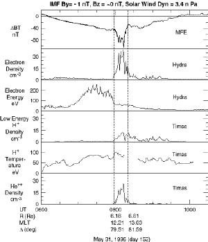
Figure 1.
Examples of polar cusp crossings for May 31, 1996. The upper panel shows the residual of the magnitude of
POLAR MFE data with Tsyganenko 96 model. The second and third panel show the Hydra electron density and energy.
The forth and fifth panels show the Timas low energy range H+ density and temperature. The bottom
panel shows the He++ density. The vertical dashed lines indicate the polar cusp crossings.

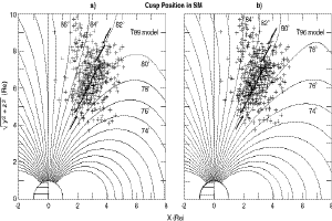
Figure 2.
The polar cusp crossings in x-r
plane in the SM coordinates. The field lines shown are from a)
Tsyganenko 89 vacuum model, b) Tsyganenko 96 model. The short bars are the medians in the
regions perpendicular to the field lines from Tsyganenko 89 vacuum model.

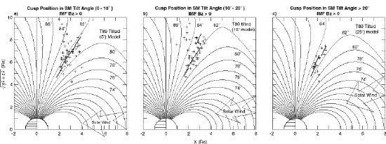
Figure 3.
The cusp position in x-
r plane in SM for tilt angle a) (0°
,10°), b) (10°,20°), and
c) >20°. The field lines are from Tsyganenko 89 vacuum model with a
tilted dipole of a) 5°, b) 15°, and c) 25°. The bars are the medians.

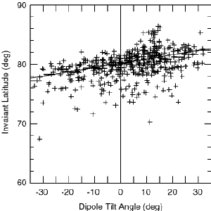
Figure 4.
The tilt angle versus the invariant latitude of the center of the cusp crossings. The bars are the medians.


Up: The Polar Cusp Location and Dipole Tilt
Previous:
References


