Abstract. Data obtained during a 2-hour sequence of multiple crossings of the magnetopause in the equatorial plane near 0900 LT with the Ogo 5 UCLA triaxial fluxgate magnetometer and electron spectrometer show that the magnetopause motion was composed of two different oscillations: large-amplitude oscillations with periods from 3.5 to 6 min, and smaller amplitude oscillations with periods as short as 10 sec. The amplitude of the short-period oscillation increased abruptly when the magnetosheath field turned 90o southward, producing an extremely variable boundary. The particle boundary showed the same oscillations as the magnetic field boundary, but the two were not coincident and their relative position was quite variable. The direction of the normal to the magnetopause during successive crossings shows that these oscillations do not represent pulsation of the whole boundary but are ripples moving tailward with a velocity of the same order as the plasma flow velocity. The observed structure of the boundary was not consistent with a rotational discontinuity. Since the component of the magnetic field normal to the boundary was often nonzero, however, the structure was not consistent with a steady state tangential discontinuity either.
The observation of the motion and structure of the magnetopause has been the topic of many papers in recent years [Holzer et al., 1966; Heppner et al., 1967; Sonnerup and Cahill, 1967, 1968; Hyde, 1967; Cummings and Coleman, 1968; Kaufmann and Konradi, 1968]. The importance of this topic lies in the fact that a clear understanding of the magnetopause would enable one to estimate the validity of the so-called open or closed model of the magnetosphere [Dungey, 1961; Beard, 1964], to check the various theories relating to the instabilities of the boundary [Sen, 1965; Parker, 1967a, b; Lerche, 1967; Southwood, 1968; Alpers, 1969; Karlson, 1970] and to understand the origin of the drag at the magnetosphere boundary. This drag or transfer of momentum through the boundary is evidenced by the existence of the magnetotail and by the direction of the plasma flow at the boundary [Freeman et al., 1968; Warren and Freeman, 1970], but there is no present agreement as to the exact physical mechanism involved in the drag [Piddington, 1960; Dungey, 1961; Axford, 1964; Siscoe, 1966; Tsuda, 1967; Eviatar and Wolf, 1968; Coleman, 1970; Cassen and Szabo, 1970]. In this paper we present some observations of the boundary motion and structure at times of large drag and indicate the relevance of our observation to the problems described.
A previous paper reported [Aubry et al., 1970] that on March 27, 1968, the inbound Ogo 5 satellite recorded an inward motion of the magnetopause of about 2 RE in two hours. In this sequence of events, a reversal of the vertical component of the interplanetary magnetic field was immediately followed by an inward motion of the magnetopause caused by an erosion of the magnetosphere; magnetic flux was carried into the tail, and the growth phase of a substorm. began about half an hour later. The velocity of the inbound Ogo 5 satellite roughly matched the average inward velocity of the boundary during about 2 hours, which enabled us to study the motion and structure of this boundary for a relatively long period of time. Moreover, Ogo 5 was transmitting at its highest data rate throughout this period, providing 56 vector samples of the field per second (sps), which allowed us to analyze the fine structure of the boundary.
We will conclude that our observations do not fit any steady open or closed model of the magnetosphere, that the motion of the boundary is at least not inconsistent with the Kelvin Hehnholtz instability hypothesis, and that the existence of an observed variable magnetic field component normal to the boundary could account for the drag responsible for the erosion of the dayside magnetosphere.
EXPERIMENT
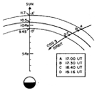
Orbit. Some general comments about the Ogo 5 orbit were made by Aubry et al. [1970]. For convenience, Figure 1 shows the projection of the Ogo 5 orbit in the GSM equatorial plane at the time of our observation. Between 1700 and 1916 UT the distance between Ogo 5 and this GSM equatorial plane varied from 1.7 to 0.04 RE, and so our measurements were performed essentially in this equatorial plane.
Magnetic field measurements. The UCLA fluxgate magnetometer was designed to provide an accurate triaxial vector measurement of the magnetic field from perigee at low altitudes to apogee in the interplanetary medium. Each of three orthogonal sensors has a dynamic range of ± 64,000 nT and in low fields can resolve field changes of 1/8 nT. This was accomplished with a basic magnetometer that measures ± 16 nT and a set of coils that provide fields to null out the field at the basic magnetometer to within ± 16 nT. The currents for the coils are provided in 64 steps of 16 nT and 128 steps of 1024 nT. This is accomplished as follows: if a field of greater than +16 or less than -16 nT reaches the basic magnetometer, this field is reduced in steps of 16 nT until the field at the basic magnetometer is within its operating range. When all available 16-nT steps have been applied (64 possible), a field of 1024 nT is applied, and 63 of the 16-nT steps are removed. This stepping procedure has a cycle rate of 500 Hz, which is far above the magnetometer sampling rates.
 | Fig. 1.Projection of the orbit of Ogo 5 in the GSM equatorial plane at the time of the observations. The extreme extrapolated positions of the boundary are shown. |
The measured field consists, then, of three quantities: the number of 1024-nT nulling fields applied, the number of 16-nT nulling fields, and the output of the basic magnetometer from +16 to -16 -nT digitized in 256 parts, each 1/8 nT. The sum of these three quantities for each independent axis gives the measured vector field.
The basic magnetometer is operated as a closed loop magnetometer with a frequency response that is flat to 150 Hz and then rolls off at 20 db per decade above 150 Hz. The three possible Ogo 5 telemetry rates, 1, 8, and 64 kilobits; per sec, correspond to Nyquist frequencies of 0.43, 3.5, and 27.8 Hz for the instrument. Since meaningful wave studies can be performed only if no signals above the Nyquist frequency reach the telemetry system, the output of the basic magnetometer enters a filter dependent on bit rate before being digitally sampled. This critically damped fourth-order filter has 8-db attenuation at half the Nyquist frequency, 20-db attenuation at the Nyquist frequency, and 40-db attenuation at twice the Nyquist frequency.
The satellite can simultaneously transmit data to earth (real time data) and store data on the spacecraft on magnetic tape for later transmission (playback data). These data can be sampled at different rates: playback data are always sampled at 1 kbit per see, whereas the real time data have three possible rates. Thus, the instrument actually has two outputs, each with its independent filter depending on the sampling rate of the digitization unit to which the signal is routed.
The absolute accuracy of the measured field depends on many factors: the sensitivity of the magnetometer, the size of spacecraft fields and the possibility of drifts in the zero levels of the magnetometer. This magnetometer is the most sensitive fluxgate magnetometer ever flown on a spacecraft and is separated from the main body of the spacecraft by a 20-foot boom. There are other nearby experiments, however, and this was a newly designated magnetometer. By comparing it with the Goddard magnetometers on board, which are on a similar boom restricted only to magnetometers, we found that there was a slow drift from orbit to orbit of the apparent zero levels of the UCLA magnetometer. The Goddard magnetometers consist of an Rb vapor magnetometer and a fluxgate magnetometer, both of which have flown before on Ogo 1 and 3, and which provide consistent fields when compared. Data from these magnetometers, graciously supplied by the experimenters, have been used to determine the zero level for each Ogo 5 orbit. In view of the slow drift of the zero levels, however, the absolute value of any one component may be in error from 1 to 2 nT. On the other hand, the rate of drift is exceedingly slow as compared with the time scales of physical processes such as waves, discontinuities, etc. Thus changes in the field components can be accurately measured to the digitization window of the experiment, 1/8 nT.
Particle flux measurements. The pitch angle electron spectrometer was designed to measure the differential unidirectional flux of electrons in the energy range from 45 to 1200 keV. It consists of six approximately coplanar independent detectors, with one pair aligned back to back and the other four spaced out through 90o relative to the first pair. The detectors, each of which contains a plastic scintillator and a photo multiplier tube, make simultaneous measurements of electron flux in a cone of half-angle 6o and are capable of analyzing particle energies in eight logarithmically distributed intervals. The measurements are transmitted to earth (real time data) whenever possible or, alternatively, are stored on tape for later transmission (playback data). The maximum usable count rate corresponds to a unidirectional flux of 103 electrons/cm2/sec/ster.
During the period of interest on March 28, 1968, the satellite telemetry rate was 64 kbits/sec, at which rate measurements are made in all detectors every 0.02 sec. The experiment was switched at 10-min intervals from the energy mode, in which all detectors repeatedly cycled through eight energy channels, to the pitch angle mode, in which only total flux in the energy range was measured.
The total flux in energy mode is obtained by averaging the differential flux over an integral number of cycles. Because the averages used in this paper are taken over 70 cycles, the problem of short time variations is not critical. The statistical uncertainty (calculated on the basis of Poisson statistics and the digitization effects resulting from use of a prescaler) is less than 103 electrons/cm2/sec/ster in pitch angle mode and is less than three times this in energy mode.
MHD DISCONTINUITIES
It is generally agreed that the magnetopause must be mainly an MHD tangential or a rotational discontinuity, the characteristics of which are shown in Figure 2 [Landau and Lifshitz, 1960]. In this figure, p, v, and p are the density, flow velocity, and pressure of the plasma; H is the magnetic field, and subscripts n and t refer to the components normal and tangential to the boundary. The square brackets represent the difference between the quantity on the two sides of the discontinuity.
The theory does not define the variation of the field inside the discontinuity. We know only that for a rotational discontinuity, the projections H1 and H2 in the plane of the boundary of the magnetic field on either side should be equal in magnitude, that a normal component of H can exist, and that the direction H1 -H2 = [Ht] must be parallel to the vector [vt]. This last requirement is in fact a very useful test; at the position of Ogo 5 (equatorial plane near 0900 LT) the plasma flow velocity in the magnetosheath must be mainly horizontal. We do not know the plasma flow velocity in the magnetosphere, but it must be smaller there than in the magnetosheath; the difference [vt] between a large horizontal vector and a small vector is roughly horizontal and in any case cannot be consistently vertical. If the boundary was a rotational discontinuity, then [Ht] would have to be roughly horizontal also. Thus, we claim that the observations of vertical vectors [Ht] presented below are inconsistent with rotational discontinuities.
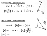 | Fig. 2.Basic relations for tangential and rotational discontinuities. The projection of the magnetic field vectors on the two sides of the discontinuity, in the plane of this discontinuity, are shown on the right. |
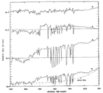 | Fig. 3.Variation of the magnetic field versus universal time on March 27, 1968. The GSM reference system is used; BT refers to the total field. |
MOTION OF THE BOUNDARY
The average inward motion of the boundary between 1700 and 1900 has already been reported by Aubry et al.[1970], who showed that boundary oscillations superposed on the main inward motion resulted in multiple crossings. We are interested here in detailed study of the boundary oscillations.
Figures 3 and 4 present our data. Figure 3 (reprinted from Aubry et al. [1970]) shows the 1-min averages of the magnetic field in the geocentric solar magnetospheric (GSM) coordinate system from 1500 to 2100 UT. The sequence of multiple crossings occurs between 1700 and 1916. The magnetic field and particle data are shown in Figure 4, which consists of three panels, each referring to the same time interval and containing 40 min of data. The top line in each panel represents 4.6-sec averages of B1, the component of the magnetic field along the axis 1 of the satellite reference system (in which the axes are labeled 1, 2, and 3). For the period considered, this axis is nearly antiparallel to the ZGSM axis (the angle varies between 170o and 180o), and crossings of the magnetopause appear as reversals of B1, which is positive in the magnetosheath and negative in the magnetosphere. To avoid any ambiguity, the two regions are labeled in Figure 4 for the first crossings. The middle line represents 10-sec averages of the particle fluxes for electrons with energy greater than 50 keV. These fluxes were computed from the readings of detector 5, which was oriented at the largest pitch angle. Flux greater than 4 x 10⁴ particles/cm2/sec/ster is indicated by a straight line, while gaps in the curve occur where data are not available. The bottom line of each panel represents the total magnetic field amplitude.
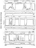 | Fig. 4.Variation Of the magnetic field and particle flux versus time from 1719 to 1919 UT on March 27, 1968. The numbers 1 to 6 refer to crossings discussed in section on boundary structure. The particle flux unit is 104 particles/cm3/sec/ster (see text). |
 | Fig. 5.Schematic models of an equatorial section of the boundary. |
The first clear encounter of the boundary took place at 1700 UT (Figure 3), when the geocentric distance of the satellite was 12.8 RE, (point A in Figure 1). The field amplitude was about the same on both sides of the boundary; only the horizontal component varied. Whereas no particles were detected before 1700, a detectable flux of energetic electrons appeared at 1700 and was observed till 1731 (see Figure 4), thus verifying that the satellite entered the magnetosphere at this time. This fact is also confirmed by the JPL solar wind experiment and the Lockheed ion mass spectrometer on board Ogo 5. At this time the field in the magnetosheath was northward, and it appears from Figure 3 that there was essentially one single crossing. By looking at 4.6-sec average data, we checked that the small oscillations just before 1700 in Figure 3 were in fact three partial crossings. At this time, therefore, the boundary was not perfectly steady; small-amplitude oscillations of 1- to 3-min periods were present, but their amplitude was much smaller than that of the oscillations observed after 1730 UT.
At 1730 after the reversal of the field in the magnetosheath (as already discussed by Aubry et al. [1970]), the sequence of multiple crossings began (Figures 3 and 4). To interpret these crossings, we will refer to two models of boundary as sketched in Figure 5. Model a presents a superposition of large-amplitude oscillations with periods (T1) of several minutes, and small-amplitude oscillations with periods (T2) of less than 1 min. In model b the short-and long-period oscillations are again superposed but with approximately the same amplitude.
From 1730 to 1840 UT (points B and C in Figure 4), the occurrences of short-duration multiple crossings appear at well-spaced intervals, and the observations can be interpreted in terms of model a. The long periods, T1, range from 3.5 to 6 min, and the short ones, T2, can be as short as 10 sec. For instance, at 1807 a sequence of partial crossings occurs (the one labeled 2 in Figure 4 will be studied in detail in the next section and will be shown to correspond to a 10-sec oscillation of the boundary). Between about 1840 and 1903, as discussed by Aubry et al., the magnetosheath field turned more southward; this produced a new inward motion of the boundary and the multiple crossings observed between 1840 and 1906 present a quite different aspect from the former ones. Since now the short-duration multiple crossings occur almost continually, they can be explained in terms of model b (Figure 5), with a long period, T1, of about 5 min and a short period, T2, of about 1 min or less. Some minutes after 1900 the magnetosheath field again became less southward, and the two last crossings at 1912 and 1915 reflect this situation. That is, the relative amplitude of the short-period oscillation has somewhat decreased.
Prior to the reversal of the magnetosheath field at 1730, the peak flux observed by the energetic electron spectrometer is 4 X 10⁴ particles/cm2/sec/ster. After 1730 the peak flux measured inside the magnetopause increases by an order of magnitude. Oscillations in intensity of the electron flux with periods of several minutes, consistent with the model of large-amplitude oscillations of the boundary, occur in the regions inside the magnetopause between 1730 and 1844 and after 1905. The period between 1844 and 1905 is characterized by rapid variations in the electron flux, frequently with periods of the order of 1 min, and lower peak intensities. Although the oscillations of several minutes period as recorded by the particle experiment are in general agreement with the oscillations of the magnetic field, Figure 4 shows that the relative position of the magnetic field and particles boundaries are variable: obviously the picture of a magnetic field boundary dividing two regions with and without energetic particles is too simple.
To be more specific about the motion of the boundary we describe the motion of the wave forms sketched in Figure 5. Are they drifting from the front of the magnetopause toward the tail, are they standing, or are they coming from the tail, and what is their velocity? This problem is an important one, because to compute the thickness of the boundary from the time duration of the observed crossings, we must know the velocity of the boundary relative to the satellite. Quite generally, only the velocity normal to the quiet boundary is computed [Holzer et al., 1966; Smith and Davis, 1970). However, it appears from theoretical studies that the magnetopause is often unstable relative to the Kelvin-Helmholtz instability [Sen, 1965; Southwood, 1968], especially when, as in our example, the plasma flow velocity is normal to the magnetic field. It is therefore quite probable that the oscillations we observe are a consequence of a Kelvin-Helmholtz instability of the boundary. If this is so, Southwood [1968] has shown that the motion of the boundary is produced by the superposition of two MHD waves propagating parallel to the boundary with opposite phase velocity on either side. If the tailward plasma flow velocity parallel to the boundary is U inside the magnetosphere and U + V just outside the boundary, the motion of the waveforms in Figure 5 should be tailward with a velocity of order U + (V/2).
In the next section we show that the multiple crossings can correspond to the tailward drift across the satellite of ripples, such as sketched in Figure 5, with a velocity of the same order as the plasma flow velocity. This is not inconsistent with the hypothesis that such oscillations are produced by the Kelvin-Helmholtz instability and indicates that the oscillations are not pulsations of the boundary as a whole.
STRUCTURE OF THE BOUNDARY
We shall now study some characteristic crossings in our 2-hour period of observation. For that purpose we shall use the eigenvalue technique discussed in the Appendix. The magnetic field will be presented in the reference system xyz of the eigenvectors: x (largest eigenvalue) is roughly vertical and is arbitrarily oriented positive upward; z (smallest eigenvalue), normal to the boundary, is generally roughly horizontal and is arbitrarily oriented positive outward. As a consequence, y (intermediate eigenvalue), which is also roughly horizontal, is positive tailward, and the xy plane is the plane of the boundary.
The directions of the z and x axes corresponding to the smallest and largest eigenvalue for some of the crossings before 1840 are shown in Figure 6 in the GSM reference system; 1-sec averages were used to compute these eigenvectors. Each point represents the tip of the projection of unitary x (circle) or z (arrow) vectors on the XY GSM plane. Circles corresponding to angles of 30o, 45o, and 90o with the GSM Z axis are shown. The arrow labeled z and the circle labeled x correspond to the unperturbed boundary. The cross section of this boundary in the GSM equatorial plane has already been defined in an earlier paper by the relation
![]()
 = 0.35. The satellite is not exactly in the GSM equatorial plane at the time of observation; to compute x and z, a magnetopause axisymmetric around the earth-sun line is assumed.
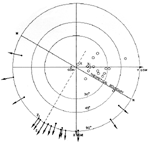 | Fig. 6.Projection on the XY GSM plane of the tips of unitary vectors parallel to the largest eigenvectors (x in the text, open circles in the drawing) and the smallest eigenvectors (z in the text, arrows in the drawing) for several crossings. z1 and x1 refer to the first crossing studied (see text). z and x refer to the unperturbed boundary. The circles indicate the locus of constant angle 30o 45o, and 90o with the Z GSM axis. |
As explained in the appendix, there can be a considerable scatter of the eigenvectors computed from different time intervals even within one particular crossing. Each individual direction in Figure 6 should not be considered as meaningful, but one should examine the general trend of the pattern. That is, the x directions (circles) make angles generally less than 30o with the GSM Z axis; the z directions are extremely variable roughly in the horizontal plane, so the waveforms of Figure 5 would correspond roughly to an equatorial cross section of the boundary. This corresponds to a fluting of the magnetopause and is in agreement with the results of Kaufman and Konradi [1968].
The sequence of crossings from 1700 to 1916 can be divided into three parts. The first one around 1700, when the magnetosheath field is upward, is characterized by the absence of important fluctuations of the boundary (Figure 3). The second interesting zone extends between B and C (Figure 4) and represents a less stable state of the boundary following the partial reversal of the interplanetary field. The crossings numbered 1 to 4 in this zone will be discussed more extensively. The third zone after C (Figure 4) represents a more unstable state of the boundary following the total reversal of the interplanetary field as already discussed by Aubry et al. [1970]. The crossings labeled 5 and 6 will be discussed. We shall try to determine whether or not the various states of unstability and the different drags observed in these three parts of the data are associated with a specific structure of the boundary.
First Zone
In the first zone, the crossing at 1700 has been studied. When examined with the 1-sps data, it consists mainly of a rotation of the field lasting about 15 sec with no normal component; the computed average for Bz, is less than 10-2 nT and thus is less than the digitization error of the experiment. The crossing was then broken into portions of about 2-sec length, and the eigenvalue analysis was performed for each by using the 56-sps data. This analysis confirmed that the boundary had a rather steady orientation during the whole crossing. However, the components of the magnetic field normal to the boundary varied from 10 to -10 nT from one interval to the other. This could be due to the presence of waves inside the boundary.
Second Zone
Crossing 1. The orientation of the eigenvectors for this boundary are shown in Figure 6, where for convenience they are labeled x1 and z1. It appears that the z1, axis is very close to the direction of the unperturbed boundary normal.
The variation of the three components of the magnetic field in the reference system of these eigenvectors is shown in Figure 7 with a sampling rate of 56 sps. The characteristic features of this crossing are: reversal of Bz maximum of By inside the boundary, compressional oscillations of about 4-sec period and 5-nT amplitude inside the boundary. The average Bz component, as computed from the 1-sec averaged data, is 2.4 nT.
The variation of the tip of the 1-sec averaged magnetic field in the plane of the boundary as seen from the earth is shown in Figure 8. This variation is mainly a rotation, and the two dashed-line circles centered at C have been drawn for visual convenience. However, the ratio
![]()
which should be zero for a rotational discontinuity, is 0.3, and the direction H1 - H2 is mainly vertical (see the direction of xi in Figure 6). These two facts refute the hypothesis that crossing 1 is a rotational discontinuity (see above). To check the 2.4-nT normal component, the crossing was then broken in intervals of 2 see length and each was analyzed by using the 56-sps data. The computed normals to the boundary were rather scattered, and the corresponding normal components ranged from +4 to -23 nT. Even if we ignore this last value, there was so much scatter in the normal field that it is probable that the motion of the boundary prevents drawing any conclusion from the various normal components obtained, so we do not know if crossing 1 corresponds to a tangential discontinuity. Our main purpose in presenting this crossing was to show an example of a rotating magnetic field across a boundary that is not a rotational discontinuity.
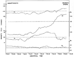 |
Fig. 7.Variation of the magnetic field through crossing 1 as seen in the reference system xyz of the eigenvectors. The sampling rate is 56 sps. |
 |
Fig. 8.Evolution of the tip of the projection of the magnetic field in the plane xy of the boundary for crossing 1. Points are 1 sec apart. |
Crossing 2. This is a double crossing; the satellite, which is first in the magnetosphere, crosses through a bump in the boundary and makes a short excursion into the magnetosheath lasting several seconds. To study this part of the data, we selected an interval of 21 sec, which contains the spike labeled 2 in Figure 4. Figure 9 shows the variation of the magnetic field in the reference system (1, 2, 3) of the satellite with a sampling rate of 56 sps.
To study the magnetic field in a more convenient reference system, an eigenvalue computation from the 1-sec averaged data was performed for this interval. This allows us to separate the Bz component, which reverses at each crossing from the By and Bz components. We assume that V, the average direction of the field in the yz plane, is also the direction of the plasma flow that carries the frozen-in field, as well as various bumps on the boundary surface. Each second we plot along V, starting in a, the direction of the field projection on yz (arrows) and the amplitude of the Bz component (Figure 10). By assuming that at any instant in time the amplitude and orientation of the field are constant along a direction perpendicular to V, the direction of the flow, we draw the projection of lines of force in the plane yz. The resultant sketch of the boundary explains simultaneously the variation of amplitude and the orientation of the field. Between points a and d the whole picture is self consistent; namely, given the position of the first crossing at b and the orientation of the field during the following 10 sec, one can predict the position of the second crossing at c. Moreover, the values of the Bz component of the magnetic field around the crossing c can be predicted from their values around the crossing b. This is no longer true beyond point d (Figure 10), where a change in orientation and/or amplitude of the plasma flow probably occurs.
 | Fig. 9.Variation of the magnetic field during spike 2 as shown in the reference system of the satellite. Br is the total field. A zero base line is drawn for each component. A sampling rate of 56 sps is used. |
 | Fig. 10.Shape of the boundary at the time of spike 2. The circled numbers are the values of Bz in nT, computed from 1-sps data; the associated short arrows give the direction of the field projection in the zy plane. On the left are shown various relevant directions as seen in the GSM equatorial plane (see text). |
For each crossing, b and c, the eigenvecters nb and nc normal to the boundary were computed from the high time resolution data (56 sps). They are shown in Figure 10 (bottom left). The orientation obtained for nb is in agreement with the general shape of the boundary. On the other hand, the agreement is not as good for nc. Owing to the great variability of the boundary at this time, we did not try to obtain a better agreement for nc by selecting several time intervals. The variation of the magnetic field during crossing b, as seen in the reference system of the boundary, is shown in Figure 11. The whole crossing b lasts about 1 sec between M and N. The reference system used is the one corresponding to eigenvectors for crossing b alone. Except for the large difference in time scale (1 instead of 10 sec), the pattern is very similar to that observed in crossing 1 (Figure 7), namely, reversal of Bz, maximum of By inside the boundary, and fluctuations of Bz around some average value (~ -0.5 nT).
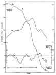 | Fig. 11. Variation of the magnetic field through crossing b (Figure 10) as seen in the reference system xyz of the eigenvectors. |
We think that the usefulness of our method for reconstructing the shape of the boundary is confirmed by the coherency of the results obtained. However, we must emphasize its drawbacks. The method would be exact for a rippled tangential boundary embedded in plasma flow with a velocity uniform in space and constant in the interval of time of the chosen sample, here about 20 sec, and if the frozen field hypothesis is satisfied. We know that all these conditions are not met; for instance, in the crossing c we obtain a normal component of about 4 nT, and around point d there is some change in the plasma flow. Finally, the instantaneous direction of the plasma velocity, assumed to be parallel to V, at about 30o from the unperturbed boundary for 20 sec, is justified only by the results obtained. Owing to these limitations, Figure 10 can give only qualitative information about the shape of the boundary, but we think that this information is useful. Namely, the very rapid oscillation of the field as exemplified by the spike labeled 2 in Figure 4 is consistent with the tailward drift across the satellite of small ripples on the boundary.
It is possible to obtain some information about the distances involved in the model of Figure 10. From the Explorer 35 measurements we know some parameters of the solar wind: temperature, Ts = 9 X 10⁴ oK; velocity, Vs = 470 km/sec; Alfvén Mach number = 6.2. From the model of the plasma flow around the magnetosphere for an Alfvén Mach number of 8 [Spreiter and Alksne, 1969], the value of these same parameters can be determined for the point of observation (equatorial plane, 0900 LT). We obtain
V = 0.4 Vs = 200 km/sec
T = 19 Ts = 1.7 X 10⁶ oK
Let us assume that during 13 sec, between points a and d of Figure 10, the velocity V of the plasma flux was oriented along OV. This gives us a distance bc, which is half a wavelength of the ripple, of 200 X 9 = 1800 km ~ 0.26 RE. What was the thickness of the boundary at this time? At b the satellite crosses the boundary in 1 sec, at an angle of about 45o. This gives a boundary thickness of 200 X 0.7 = 140 km. The Larmor radius for 1.7 X 10⁶, oK protons in a 40-nT magnetic field is 64 km. So, the computed thickness of the boundary at b is about 2 Larmor radii. Theoretically this thickness is a minimum for a reversal of the field, and, consequently, the assumed velocity of the ripple is a minimum too. This verifies that the ripple responsible for spike 2 in Figure 4 has to move tailward with a velocity at least of the same order of magnitude as the plasma flow velocity.
Crossing 3. The position of this crossing in the whole sequence, is shown in Figure 4. Crossings 3 and 4 have been studied successively and in more detail than the former ones. Indeed, they are less than 2 min apart, which gives an opportunity to study the important changes occurring in the boundary during very short intervals of time. Moreover, they seem to be 'clean' with the time definition of Figure 4, and this will allow us to show the importance of high sampling rates for studying the magnetopause. We wanted to check carefully on these crossings the tailward drift hypothesis as well as the existence of variable components of the field normal to the boundary. This led us to perform several eigenvalue computations for each crossing (see appendix).
In regard to crossing 3, we first examine the variation of the magnetic field across the boundary. We must select some of the time intervals presented in the appendix: first the interval n11 (Figure 18) is chosen because it represents 1-sec averaged data for the whole crossing (about 10 sec). In Figure 12 the variations of B in the reference system of the boundary (computed from the n11 interval data) are shown. The classical signature of the boundary appears: reversal of Bx, maximum of By, and oscillations in Bz around an average value (5 g ). These features are very similar to those of crossing 1 (Figure 7) or 2 (Figure 11). To look in more detail at the region of the field reversal, we choose the time interval N7 (Figure 18), which contains 56-sps data for this region.
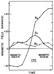 | Fig. 12. Variation of the magnetic field component in the eigenvector reference system xyz for interval n11 (crossing 3, Figure 18). Points are 1 sec apart. |
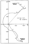 | Fig. 13. Evolution of the tip of the projection of the magnetic field in the plane xy of the boundary for interval N7, (crossing 3, Figure 18). The points are 1.7 X 10⁻² sec apart (56 sps). The dashed lines are drawn to emphasize the regions where  B is parallel to B. The average value of Bz (3-5 10-2 nT) for the interval AB is less than the digitization error of the instrument and so is equivalent to zero.
 |
In Figure 13 the variation of the projection of the magnetic field in the plane xy of the boundary (computed from the N7, interval data) is shown as seen from the earth. This variation should be compared with the rotation in Figure 8. During the interval AB, the corresponding Bz component varies between -2 and +2 nT, with an average of 3.5 X 10⁻². If we compute the average Bz component over the whole N7 interval, the result is somewhat different (-0.5 nT, as indicated in Table 1). This result emphasizes the difficulty of measuring the component of the field normal to the boundary. It appears that the structure of this part N7 of the crossing, which lasts less than 2 sec, is rather complicated: a central section NP nearly force-free is squeezed between two intervals MN and PB, where opposite Lorentz forces normal to the boundary are maximum (B and  B are nearly parallel in these two intervals). In fact, the use of magnetohydrodynamic concepts should be considered here with caution, because it will be shown that the total thickness of the boundary during crossing 3 is of the order of 3 Larmor radii.
In regard to the existence of a normal component of the magnetic field to the boundary, we conclude in the appendix that no clear result can be drawn for this particular crossing.
Crossing 4. The position of this crossing in the whole sequence is shown in Figure 4; it occurs less than 2 min after crossing 3, and we will use for 4 exactly the same kind of analysis as for 3. A discussion of the eigenvalue analysis is presented in the appendix. To study the variation of the magnetic field across the boundary, we first select the interval ns, which represents 1-sec averaged data for the whole crossing (Figure 19). In Figure 14 the variations of B in the reference system of the boundary (computed from the ns interval data) are shown. The reversal of Bz and the maximum of By are observed. We chose the interval N6, (56 sps) to look in more detail at the region of the field reversal. In Figure 15, the variation of the projection of the magnetic field in the plane of the boundary (computed from the N6 interval data) is shown as seen from the earth; we observe mainly a rotation. During this interval the corresponding Bz component varies between 11.3 and 12.6 nT with an average of about 12 nT. The variation of the field in Figure 15 is very smooth, and we think that the observed normal component of 12 nT is not produced by time-dependent fluctuations. We conclude from the discussion in the appendix that in crossing 4 there is a component of the magnetic field normal to the boundary; yet, this crossing does not correspond to a rotational discontinuity.
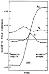 | Fig. 14. Variation of the magnetic field components in the eigenvector reference system for interval ns (crossing 4, Figure 19). Points are 1 sec apart. |
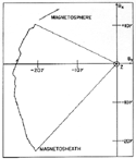 | Fig. 15. Evolution of the tip of the projection of the magnetic field in the plane xy of the boundary for interval N6. (crossing 4, Figure 19). The points are 1.7 X 10⁻² sec apart (56 sps). |
Another aim of the study of crossings 3 and 4 was to check the tailward drift hypothesis. For this purpose we consider these two crossings together. It is obvious from Figures 18 and 19 that a change in the orientation of the boundary occurs between crossings 3 and 4. For crossing 3 the average normal can be assumed to be roughly parallel to the X GSM axis (see appendix); for crossing 4, the direction of the N5 arrow is chosen. Figure 16 summarizes our feeling about the shape of the boundary at the time of crossings 3 and 4, when we neglect the short-period oscillations. The angles of 30o indicated in Figure 16 are not claimed to be meaningful to better than ± 10o. The important point we emphasize is that the relative orientation of the two normals associated with the fact that 3 is observed before 4 implies that the structure AMB moves toward the tail.
 | Fig. 16. Sketch of the boundary at the time of crossings 3 and 4 (not to scale). |
What are the dimensions involved in this structure? First, we make the assumption that its tailward velocity is the velocity of the plasma flow (200 km/sec) parallel to the unperturbed boundary. The distance AB represents 2 min, or 120 x 200/6.4 103 ~3.5 RE which can be compared with the 0.3 RE obtained in the case of spike 2 (distance be in Figure 10). To evaluate the thickness of the boundary, we must correct for the oscillations occurring during the crossing. The technique used is simple: from the slope of the unperturbed part of the crossing we evaluate graphically the duration of this crossing in the absence of oscillation. From Figures 18 and 19 this gives about 2 sec for crossings 3 and 4. The angle between the velocity (200 km/sec) and the boundary is ± 30o for the two crossings; we obtain a thickness of 200 km equivalent to 3 proton Larmor radii. Alternatively, if this boundary thickness is considered reasonable, our result checks that the order of magnitude assumed for the velocity of the boundary was correct. So for the short or long-period oscillations of the boundary (spike 2, or the pattern defined by crossings 3 and 4), we reach identical conclusions: these oscillations are consistent with ripples on the boundary, drifting tailward with a velocity of the same order of magnitude as the plasma flow velocity.
Third Zone
For the third zone of crossings after 1840, we tried to analyse the spikes labeled 5 and 6 in Figure 4 by the technique already used for spike 2, but this attempt was unsuccessful. Although no conclusion can be shown for this third zone, we think that it is useful to present a short account of the difficulties involved. Spike 5 appears very similar to spike 2 even at a resolution of 7 sps. Its duration is about the same, 10 to 15 sec, but the eigenvectors computed from the 56-sps data for five different intervals were so scattered, with components normal to the boundary ranging from -15 to +20 nT, that we were unable to devise a scheme equivalent to that of Figure 9 for spike 5. For spike 6, the high-resolution data (56 sps) presented in Figure 17 shows that a study using the eigenvalue technique is meaningless: the fluctuations are too much rapid. Figure 17 represents the total field BT and the three components of the field in the satellite reference system.
Two remarks about this spike are useful. Until 1846:30, Ogo 5 was in the magnetosheath, and some seconds later the boundary swept partially over it. The first thing recorded by the satellite just outside the boundary was a very high magnetic field peaking at 70 nT during less than 2 sec at about 1846:33; such large-amplitude fields were never recorded before 1800. After this time we have two more examples (see 1859 and 1913 in Figure 4).
Another characteristic of the boundary at this time was the very high level of oscillations with periods less than 1 sec. In this regard, it is interesting to compare Figure 17 with Figures 7, 9, 18, and 19, which show crossings 1, 2, 3, and 4 with the same sampling rate. The main conclusion to be drawn from these very brief comments about the third zone is that, owing to the great variability of the boundary at this time, one cannot assume that this boundary keeps even a roughly constant orientation during the time required for one crossing, and so the usual analysis technique fails.
DISCUSSION AND CONCLUSION
Motion of the boundary. From the observation of crossings we measured periods of several minutes and periods of less than 1 min, even as low as 10 sec. The two ranges do not seem to overlap. This is confirmed by the particle data. The long-period oscillations are well within the period range reported by Hyde [1967], Anderson et al. [1968], Kaufmann and Konradi [1968], and Smith and Davis [1970]. They are shorter than those reported by Holzer et al. [1966]. The Kelvin-Helmholtz instability is generally proposed as an explanation of these oscillations [Southwood, 1968]. We have shown on two examples (crossings 3 and 4) that the wave form associated with these oscillations drifted tailward with a velocity of the same order of magnitude as the plasma flow velocity as would be required for a wave generated by the Kelvin-Helmholtz instability.
The short-period oscillations have not yet been reported in the literature, mainly because very often the sampling rate of the data did not permit the study of short periods. This was the case for Explorer 12, for instance [Hyde, 1967; Kaufmann and Konradi, 1968]. In the case of Imp 2 the particle flux measurements were made every 40 sec; the fact that the spectrum of oscillation period obtained from Imp 2 dropped sharply below 3 min [Anderson et al., 1968] confirms that the two ranges of oscillation, several minutes and less than 1 min, are separated. We do not know if this implies two different generation mechanisms, but we have shown that the 10-sec period ripple on the boundary responsible for spike 2 was also drifting tailward with a velocity similar to the plasma flow velocity. It would be interesting to know if the fluctuation of the order of 10 sec as represented by spikes 2, 5, and 6 has a different origin from the ones with less than 5-sec periods that appear in crossings 1 (Figure 8), 2 (Figure 11), 3 (Figure 18), 4 (Figure 19), and 6 (Figure 17). We recall that the proton cyclotron period in a 30-nT magnetic field is about 2 sec. The amplitude of the long-period oscillations is generally much larger than the amplitude of the short-period ones, except during the last part of the crossings (between 1840 and 1906). It should be emphasized that this last sequence of crossings is characterized by: the most southward orientation of the magnetosheath field, the most inward position of the boundary, and the most fluctuating magnetic fields and particle fluxes. This is in contrast to the nearly steady boundary recorded at 1700, where the magnetosheath field was northward. The oscillations as recorded by the particle experiment confirmed the qualitative description obtained from the analysis of the magnetic data.
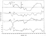 | Fig. 17. Variation of the magnetic field through spike 6 (Figure 4). The satellite reference system 1, 2, 3 is used, as in Figure 9. A zero base line is drawn for each component. A sampling rate of 56 sps is used. |
We assumed that the multiple crossings observed at the satellite are produced by the drifting toward the tail, of ripples on the boundary, with a velocity of the same order of magnitude as the average flow velocity of the plasma, (about 200 km/sec). The boundary thickness computed from this model was of 2 to 3 proton Larmor radii; if the thickness is considered reasonable, this is a rough check of the validity of our assumption on the velocity. The relative orientation of the boundary during succeeding crossings confirms that the motion was indeed tailward (a similar conclusion was reached by Kaufmann and Konradi [1968]).
Microstructure of the boundary. We analyzed more than 20 crossings; 4 representative ones are presented. Various signatures were found, as can be seen from Figures 7 to 15. Moreover, the evolution, as seen by the satellite, from one shape to the other is very rapid; for example, there is a delay of only 2 min between the structures observed in Figures 13 and 15.
Through the whole interval, however, the difference vector of the magnetic fields on the two sides of the boundary is mainly vertical. Since the measurements are made at the equator, the difference vector for plasma flow velocity should be mainly horizontal. Therefore, we claim that the results cannot fit with a rotational discontinuity model of the boundary. This is confirmed by the fact that the amplitudes of the field on the two sides of the boundary always differ by at least 20%; although the magnetic field is not measured simultaneously on the two sides of the boundary, it is evident from Figure 4 that the change in amplitude observed at a crossing is greater than the average fluctuation of the magnetosheath field, at least for the crossings prior to 1840 UT. (This is particularly clear for crossings 1 and 4). Consequently, an interpretation of these crossings in terms of rotational discontinuities is unacceptable. On the other hand, as shown above, at some of the observed crossings normal components of the magnetic field are present, so these crossings also cannot be interpreted as tangential discontinuities.
Normal component. The existence of a normal component of the magnetic field is probably the most important part of any study of the magnetopause, because it is customarily related to the open and closed models of the magnetosphere [Dungey, 1961; Beard, 1964]. From a theoretical point of view, Siscoe [1966] showed that a uniform normal component over the whole magnetopause should be roughly 10-2 nT. Many previous attempts to determine the normal component of the magnetic field experimentally failed to obtain definitive results. One reason, as discussed in the appendix, is that only high sampling rates permit the study of a highly time-dependent magnetopause. In our opinion, however, the main reason is that such a ‘definitive result’ does not exist. First, our observations show that from one crossing to another quite varying average normal components appear. In the four examples presented, these average normal components were mainly positive, but we observed also negative or inward normal components. Secondly, inside each crossing the normal component could fluctuate by several nT, which is far from negligible when compared with a total field occasionally as low as 10 nT in the middle of the current sheet. Owing to this variability, we cannot compare our results with the uniform normal component assumed by Siscoe [1966]. These various normal components, which were never associated with a structure of rotational discontinuity, are undoubtedly related to the very high drag observed at this time and already reported by Aubry et al. [1970].
This study concerns a short interval of time and consequently does not pretend to give any statistical information. However, we had the opportunity to study a very perturbed state of the magnetopause, and it is worthwhile to summarize the observations presented by Aubry et al. [1970] and in this paper. On March 27, 1968, following a reversal of the interplanetary magnetic field from northward to southward, some large-amplitude oscillatory motions developed on the magnetosphere boundary; at the same time the very structure of this boundary was quite variable, and this variability increased with the southward component of the interplanetary field. Associated with these phenomena, variable components of the magnetic field normal to the boundary were recorded and produced a large transfer of momentum across the magnetopause, leading to the erosion of the dayside magnetosphere. It must be emphasized that, during all this period of time, the observed local characteristics of the boundary, including the amplitude and orientation of the normal component as well as the counting rate of energetic electrons on either side of the boundary, were extremely variable and thus did not fit with any steady open or closed model of the magnetosphere.
APPENDIX
For the detailed study of individual crossings, the first problem is to display the variations of the magnetic field in a convenient reference system. In particular we wish to choose the x and y directions to be in the plane of the boundary and z normal to the boundary. The technique for determining this reference system is now very well known [Sonnerup and Cahill, 19671. Since B must satisfy

if we assume a plane homogeneous boundary such that

then

If s 2 is the variance of the projection, on a direction n, of a sample of N measurements of the magnetic field,


where Ba and Bb are components of an individual measured field vector in the reference system of the satellite.
The vector associated with the smallest eigenvalue is normal to the boundary. The vectors x and y associated with the largest and intermediate eigenvalues, respectively, are in the plane of the boundary. If the current inside the boundary is unidirectional, x is perpendicular to the current vector, and then y and z are undetermined.
It should be noted that the method is based on the validity of (A2) and (A3), which requires a plane and steady state boundary during the time of the analysis. A crossing as seen by Ogo 5 lasts about 10 sec, and we have shown evidence for important variations of the orientation of the boundary within such a time interval. Thus, at least in our application, (A2) and (A3) are not generally satisfied over an entire crossing. It is important, therefore, in applying the eigenvalue technique to boundary crossings, to select intervals for analysis that are short enough that the boundary remains relatively steady. In this appendix we illustrate for two crossings the effect of changing the interval of analysis across a boundary traversal and of changing the sampling rate of the data used in the analysis. For the UCLA Ogo 5 fluxgate, changes in sampling rate are equivalent to averaging the data points over different sample periods, because the data are filtered to obey the Nyquist criterion at each sampling rate.
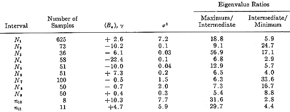
First, we make an eigenvalue analysis for crossing 3. An enlarged plot of the B1 component for this crossing measured at a rate of 56 sps is shown in Figure 18. Eigenvalue computations have been processed for 11 time intervals shown on this figure. For the intervals labeled N1 to N9, a rate of 56 sps was used; for the intervals labeled n10, and n11, 1 sps was used.
Table 1 lists the following information for these eigenvalue computations: the number of samples used to perform the eigenvalue computations, the average component Bz of the magnetic field normal to the boundary as well as the variance s 2 (equation A4) of the normal component of the field around this average value; (this of course equals the smallest eigenvalue). The ratio of the largest eigenvalue to the intermediate one and the ratio of the intermediate to the smallest one are also shown for each interval.
Table 1 shows several facts about the eigenvalue analysis. First, the field along the computed normal is quite variable, ranging from 10 to -20 nT. Second, the variance of the field along the normal can be quite small, as low as .03 nT2, and is largest for the intervals covering the longest period of time. Third, the three eigenvalues generally have quite distinct magnitudes. We shall return to the first point later. The second point implies that the boundary orientation does not change much over short periods but can move significantly over long periods. The third point means that the direction of maximum field variation (the x axis) and of minimum field variation (the boundary normal) are both well defined. However, the 56-sps data generally give a better separation of the intermediate and minimum eigenvalues than do 1-sps data, and thus we expect that the 56-sps data define the boundary normal better.
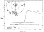 | Fig. 18. Variation of the B1 component (reference system of the satellite) versus time, through crossing 3. The sampling rate is 56 sps. The intervals labeled N1 to n11 were used for eigenvalue computations. The resulting directions of the largest (open circles) and smallest (arrows) eigenvectors are represented at the top left of the figure (same as in Figure 6). x and z refer to the unperturbed boundary. |
Table 1. Results of Eigenvalue Computation for Several Time Intervals during Crossing 3.
The directions z of the normal to the boundary (arrows) and of the x axis (circle) obtained in the 11 computations are shown at the upper left of Figure 18. The representation is the same as in Figure 6; each point (arrow or circle) represents the projection in the GSM equatorial plane of the tip of a unitary eigenvector. Circles corresponding to angles of 10o, 30o, and 90o with the GSM Z axis are shown. The dashed arrows (N2, N3, N4, and N5) represent vectors below the XY GSM plane. Except for these four vectors, all the eigenvectors in Figure 18 have a positive component along the GSM Z axis.
The variation of the boundary orientation during this crossing can be studied from the evolution of the z eigenvectors (arrows). These vectors have been grouped in three sets (shaded areas) : N2 and N3 correspond to the first 1-sec part of the crossing around 1817.08 UT; N7, N8, and N9 correspond to the last part, 2 see around 1817:12; the intermediate part lasting 3 see is represented by N4, N5, and N6. The N1 z vector is computed from the whole interval and so represents some time average of the boundary normal direction. However, one must not forget that the time spent by the satellite inside a region of the boundary at a particular time depends on the angle between the instantaneous normal and the velocity vector of this part of the boundary (a velocity vector parallel to the normal gives the shortest crossing, whereas a velocity vector parallel to the boundary gives the largest one). Consequently, the time-averaged normal (as the N1 arrow) can be different from the space-averaged normal we are interested in. For this particular crossing (3) the latter normal is probably not far from the XGSM axis. The results obtained from the 1-sps data are rather different from the results obtained from the 56-sps data even when the interval is exactly the same (n1l and N1 for instance), and we show them only to illustrate the advantage of the high time resolution data.
The largest eigenvectors (circles) are on the average not very far from the Z GSM axis (see Ni, n10, and n11), a result that would be obtained from a current sheet flowing on the average very roughly parallel to the GSM equatorial plane. However, the structure of this current sheet is rather complicated, as can be checked from the scattering of the largest eigenvectors obtained from short time samples (N2 to N9).
We now examine the eigenvalues analysis for the crossing 4. An enlarged plot of the variation of the B1 component measured at a rate of 56 sps is shown in Figure 19. Ten intervals chosen for the eigenvalue computation are delineated, and the directions of the corresponding axes x and z are shown in the upper right of the figure.
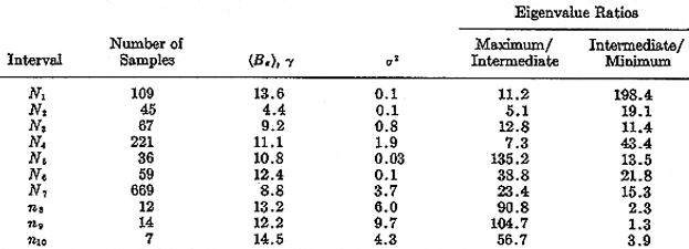
Table 2 presents the information about this set of eigenvalue computations in the same format used in Table 1. As before, the component of the field normal to the boundary varies over the different analysis intervals, ranging from 4.4 to 13.6 nT. Again the ratio of the intermediate to the smallest eigenvalue illustrates that the 1-sps data can only poorly define the direction of the boundary normal. Also, the longer intervals are associated with larger variances.
By examining Figure 19, we see that the z eigenvectors are less scattered than those in crossing 3. In fact, the main scatter is due to n8, n9, and N2. The calculation of n8 and n9 used 1-sps data that, as discussed above, poorly define the normal, and the interval over which N2 was calculated includes a bump that appears to be due to a short-period fluctuation with a period of the order of seconds, of the same type that produced an intermediate zone in crossing 3. If the three normals are ignored, the grouping of the calculated normals around some average normal direction is apparent.
The computed x axes (circles) lie as expected, roughly in a plane perpendicular to this average normal. (The intersection of this plane with the unit sphere is indicated by the dashed line.) Here again, the x axes corresponding to the long-duration samples N7, n8, n9, and n10 are closest to the Z GSM axis, which is consistent with a current sheet flowing approximately in the GSM equatorial plane. The scatter of the x vectors computed over the shorter intervals reflects the complexity of the detailed structure of the current sheet.
From an examination of the two crossings we see first that we generally cannot determine consistent boundary normals with the 1-sps data. Furthermore, even the 56-sps data may give misleading normals at times when the boundary oscillates during an analysis interval. Thus we must use the results of the eigenvalue technique with caution, requiring a consistent pattern of normals over short periods within the boundary if we are to obtain meaningful results. High data rates such as are available on Ogo 5 are essential for this purpose, although low sampling rates certainly are adequate to give a general picture of the field variation across the boundary (as in Figures 8, 10, 12, and 14).
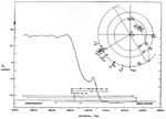 | Fig. 19. Variations of the B1 component (reference system of the satellite) versus time through crossing 4. The sampling rate is 56 sps. The intervals labeled N1 to n10 were used for eigenvalue computations. The resulting directions of the largest (open circles) and smallest (arrows) eigenvectors are represented at the top right of the figure (same as in Figure 6). x and z refer to the unperturbed boundary. |
With this in mind we can interpret the extent to which the field component normal to the boundary as derived in Tables 1 and 2 is meaningful. First, we should ignore all the components derived from the 1-sps data. In crossing 3 the various Bz components (Table 1) are very variable and are both positive and negative, so we cannot claim that a steady normal component exists during this crossing. On the other hand, if we discard the 1-sps data, the normal components obtained for the various time intervals in crossing 4 (Table 2) are rather constant and are of the order of 10 nT. The only exception is the interval N2. which is a perturbed part of the crossing. The rather steady normal component during the remainder of the crossing shows that this measured normal component is not a consequence of fluctuations in the orientation of the boundary. As the error in zero-level discussed above is less than 2 nT for each axis, a zero-level error cannot explain such a 10-nT normal component either. Thus, we see that at times there can exist large field components normal to the magnetopause.
Table 2. Results of Eigenvalue Computation for Several Time Intervals during Crossing 4.
Acknowledgments. We wish to thank the many experimenters who permitted us to examine their data for the interval covered in this paper: Drs. D. Colburn and C. Sonett of Ames Research Center for the Explorer 35 and Explorer 33 magnetic field data; Marcia Neugebauer of JPL for the Ogo 5 solar wind plasma data; Drs. S. Ossakow and G. Sharp of the Lockheed Palo Alto Research Laboratory for the Ogo 5 ion mass spectrometer data, and Drs. T. Skillman and J. Heppner of GSFC for providing us with data to check our zero levels. Helpful discussions with P. J. Coleman, Jr., F. Coroniti, T. Farley, R. Holzer, C. Kennel, and G. Siscoe are also gratefully acknowledged. The co-investigators responsible for the UCLA fluxgate magnetometer are P. J. Coleman, Jr., Thomas A. Farley, and Darrell L. Judge.
This work was supported by the National Aeronautics and Space Administration under NASA contract NAS5-9098. One of us (M. P. A.) also received support from ESRO and NASA.
The Editor wishes to thank B. U. Sonnerup and M. Sugiura for their assistance in evaluating this paper.
REFERENCES
Alpers, W., Steady state charge neutral models of the magnetopause, Astrophys. Space Sci, 5, 425-437, 1969.
Anderson, K. A., J. H. Binsack, and D. H. Fairfield, Hydromagnetic disturbances of 3 to 15 min period on the magnetopause and their relation to bow shook spike, J. Geophys. Res., 73, 2371-2386, 1968.
Aubry, M. P., C. T. Russell, and M. G, Kivelson, On inward motion of the magnetopause preceding a substorm, J. Geophys. Res., 75, 7018-7031, 1970.
Axford, W. I., Viscous interaction between the solar wind and the earth's magnetosphere, Planet. Space Sci., 12, 45-53, 1964.
Beard, D. B., The effect of an interplanetary magnetic field on the solar wind, J. Geophys. Res., 69, 1159-1168, 1964.
Cassen, P., and J. Szabo, The viscous magnetopause, Planet. Space. Sci., 18, 349-366, 1970.
Coleman, Jr., P. J., Tangential drag on the geomagnetic cavity, Cosmic Electrodynamics, 1, 145, 1970.
Cummings, W. D., and P. J. Coleman, Jr., Magnetic fields in the magnetopause and vicinity at synchronous altitude, J. Geophys. Res., 73, 5699-5717,1968.
Dungey, J. W., Interplanetary magnetic field and the auroral zone, Phys. Rev. Lett, 6, 47, 1961.
Eviatar, A., and R. A. Wolf, Transfer processes in the magnetopause, J. Geophys. Res., 73, 5561-5575, 1968.
Freeman, J. W., Jr., C. S. Warren, and J. J. Maguire, Plasma flow directions at the magnetopause on January 13-14, 1967, J. Geophys. Res., 73, 5719,1968.
Heppner, J. P., M. Sugiura, T. L. Skillman, B. G. Ledley, and M. Campbell, Ogo A magnetic field observations, J. Geophys. Res., 72, 5417, 1967.
Holzer, R. E., M. G. McLeod, and E. J. Smith, Preliminary results from the Ogo 1 search coil magnetometer: Boundary positions and magnetic noise spectra, J. Geophys. Res., 71, 1481-1486, 1966.
Hyde, R. S., Explorer 12 magnetometer observations of the magnetosphere boundary region, Pub. UNH 67-6 Department of Physics, University of New Hampshire, Durham, 1967.
Karlson, E. T., On the equilibrum of the magnetopause, J. Geophys. Res., 75, 2438-2448, 1970.
Kaufmann, R. L., and A. Konradi, Explorer 12 magnetopause observations: Large scale nonuniform motion, Goddard Space Flight Center, Rep. X-612-448, 1968.
Landau, L. D., and E. M. Lifshitz, Electrodynamics of Continuous Media, Pergamon, New York, 1960.
Lerche, I., On the boundary layer between a warm, streaming plasma and a confined magnetic field, J. Geophys. Res., 72, 5295-5310, 1967.
Parker, E. N., Confinement of a magnetic field by a beam of ions, J. Geophys. Res., 72, 2315-2322, 1967a.
Parker, E. N., Small-scale nonequilibrium of the magnetopause and its consequences, J. Geophys. Res., 72, 4365-4374, 1967b.
Piddington, J. H., A theory of polar geomagnetic storms, Geophys. J, Roy. Astron. Soc., 3, 314, 1960.
Sen, A., Stability of the magnetospheric boundary, Planet. Space Sci., 13, 131-141,1965.
Siscoe, G. L., A unified treatment of magnetospheric dynamics with application to magnetic storm, Planet. Space Sci., 14, 947-967, 1966.
Smith, E., J., and Leverett Davis, Jr., Magnetic measurements in the earth's magnetosphere and magnetosheath: Mariner 5, J. Geophys. Res., 75, 1233-1245, 1970.
Sonnerup, B. U. 0., and L. J. Cahill, Jr., Magnetopause structure and attitude from Explorer 12 observations, J. Geophys. Res., 72, 171, 1967.
Sonnerup, B. U. 0., and L. J. Cahill, Jr., Explorer 12 observations of the magnetopause current layer, J. Geophys. Res., 73, 1757-1770, 1968.
Southwood, D. J., The hydromagnetic stability of the magnetospheric boundary, Planet. Space Sci., 16, 587-605, 1968.
Spreiter, J. R., and A. Y. Alksne, Plasma flow around the magnetosphere, Rev. Geophys., 7, 11-50,1969.
Tsuda, T., Effective viscosity of a streaming collision-free plasma in a weakly turbulent magnetic field, J. Geophys. Res., 72, 6013-6020, 1967.
Warren, C. S., and J. W. Freeman, Jr., Evidence for viscous interaction at the magnetospheric boundary, preprint, Houston NASA Center, 1970.
(Received September 14, 1970;
revised November 2, 1970.)
 Back to CT Russell's page
 More On-line Resources
 Back to the SSC Home Page